

metrology

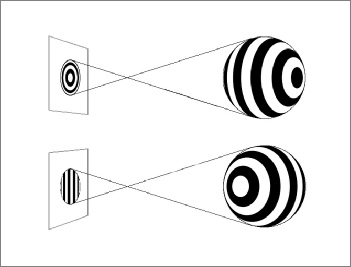
HOLOS tracking software is able to detect both the exact absolute 3D position and 3D orientation of a patterned sphere in space just from its appearance in a single 2D camera frame. Getting this full 3D information from only 2D is possible because each different position and orientation in 3D space generates a pattern on the camera’s focal plane uniquely corresponding to only this position and orientation, which therefore can be inferred from the pattern. Different orientations in 3D space for example result in different curvatures of the bands in the pattern on the camera chip, as indicated in the figure to the left, allowing the software to pick up the exact orientation of the sphere from any viewing angle.
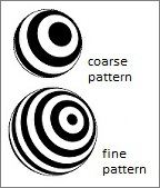
The core advantage of the HOLOS detection algorithm derives from the exceptionally high precision and robustness at which it can distinguish very slight subpixel changes of the pattern’s position, diameter and band curvature in the camera image even if the pattern appears small, pixelated and moderately out of focus. With a fine band structure on the sphere as indicated in the image to the right, pattern movements on the sensor smaller than 1/100th of a pixel unit can be detected. The accuracy even improves to better than 1/300th of a pixel unit when our Metrology optimized HOLOS algorithm is used together with a stereo setup, where twice as much pixel information is available.
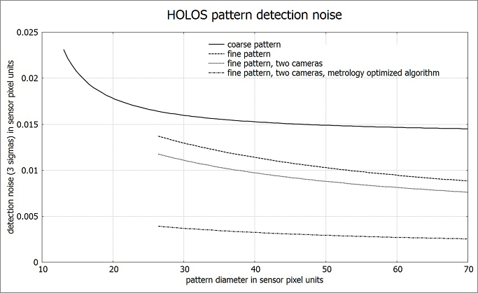
The detection accuracy for the pattern in the camera images together with the triangulation baseline directly determine the accuracy with which the 3D position of the probe tip can be detected. In the case of a single camera the baseline is the diameter of the sphere but in the stereo camera case it is the distance between the left and right camera which is on the order of 5 to 10 times larger, resulting in an improvement of the accuracy by a similar factor. In the schematics on “accuracy and range” pages 3D tip position detection accuracy is predicted based on a baseline of 500 mm and the empirically measured pattern noise shown in the diagram above. Range and accuracy are shown for various camera resolutions, a sphere diameter of 55 mm and a 36° Angle of View.
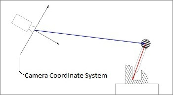
Once the software has identified both the position (blue vector in the image on the left) and the orientation (red vector) from the sphere pattern in the camera’s image, the exact 3D tip position in camera coordinates can be calculated even if no direct line of sight exists to the tip. This for examples allows cavities and recesses to be measured which cannot be scanned from a distance with other methods such as LIDAR due to occlusion.